ESP32 with PIR Motion Sensor using Interrupts and Timers#
From: ESP32 with PIR Motion Sensor using Interrupts and Timers —— Random Nerd Tutorials
电路与功能#
本教程展示了如何使用 PIR 运动传感器通过 ESP32 检测运动。在本例中,当检测到运动(触发中断)时,ESP32 会启动一个计时器,并在预定义的秒数内打开 LED。当计时器倒计时结束时,LED 会自动关闭。
检测运动: 用到中断
倒计时: 定时器(但不用 delay)
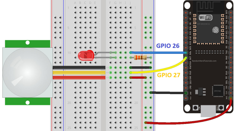
LED 连接 GPIO26
运动检测连接 GPI27
Blink with millis()#
这是一段经典的 Blink without delay 代码,无阻塞定时:
// constants won't change. Used here to set a pin number :
const int ledPin =  26;      // the number of the LED pin

// Variables will change :
int ledState = LOW;             // ledState used to set the LED

// Generally, you should use "unsigned long" for variables that hold time
// The value will quickly become too large for an int to store
unsigned long previousMillis = 0;        // will store last time LED was updated

// constants won't change :
const long interval = 1000;           // interval at which to blink (milliseconds)

void setup() {
  // set the digital pin as output:
  pinMode(ledPin, OUTPUT);
}

void loop() {
  // here is where you'd put code that needs to be running all the time.

  // check to see if it's time to blink the LED; that is, if the
  // difference between the current time and last time you blinked
  // the LED is bigger than the interval at which you want to
  // blink the LED.
  unsigned long currentMillis = millis();

  if (currentMillis - previousMillis >= interval) {
    // save the last time you blinked the LED
    previousMillis = currentMillis;

    // if the LED is off turn it on and vice-versa:
    if (ledState == LOW) {
      ledState = HIGH;
    } else {
      ledState = LOW;
    }

    // set the LED with the ledState of the variable:
    digitalWrite(ledPin, ledState);
  }
}
扩展#
这段代码经过修改后可从宏观上同时并行完成多件工作,例如「收」、「发」并行。
loop(){
  if (currentMillis - previousMillis_1 >= interval_1) {
    // save the last time you blinked the LED
    previousMillis_1 = currentMillis;

	do_something_1();
  }

  if (currentMillis - previousMillis_2 >= interval_2) {
    // save the last time you blinked the LED
    previousMillis_2 = currentMillis;

	do_something_2();
  }
}
显然,因为运行 do_something_1() 需要时间,所以这里的定时并不一定绝对准确。
中断#
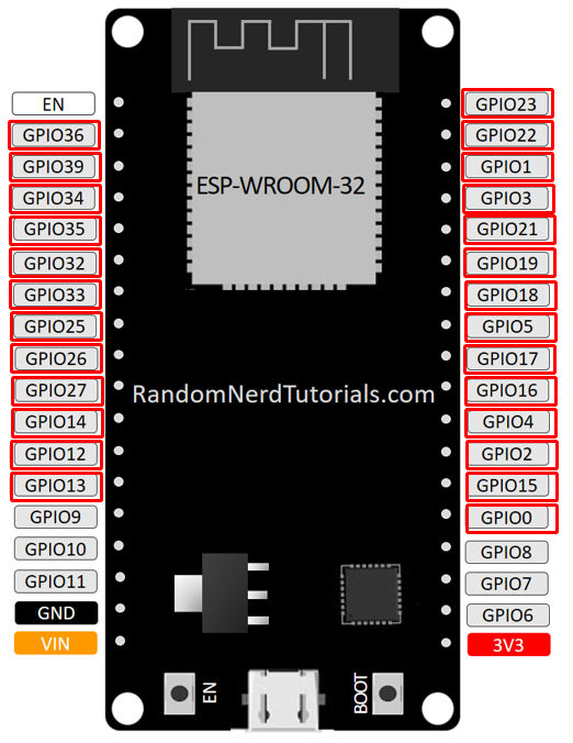
可以用作中断的引脚都用红框框起来了,例如设置 GPIO27 引脚用为输入中断
digitalPinToInterrupt(27)
attachInterrupt(digitalPinToInterrupt(motionSensor), detectsMovement, RISING);
中断引脚#
注意 GPIO27 连接 Motion Sensor
PIR Motion Sensor#

Complete Code#
#define timeSeconds 10

// Set GPIOs for LED and PIR Motion Sensor
const int led = 26;
const int motionSensor = 27;

// Timer: Auxiliary variables
unsigned long now = millis();
unsigned long lastTrigger = 0;
boolean startTimer = false;
boolean motion = false;

// Checks if motion was detected, sets LED HIGH and starts a timer
void IRAM_ATTR detectsMovement() {                      // 1
  digitalWrite(led, HIGH);
  startTimer = true;      // 可看作计时开关
  lastTrigger = millis();
}

void setup() {
  // Serial port for debugging purposes
  Serial.begin(115200);

  // PIR Motion Sensor mode INPUT_PULLUP
  pinMode(motionSensor, INPUT_PULLUP);
  // Set motionSensor pin as interrupt, assign interrupt function and set RISING mode

  attachInterrupt(digitalPinToInterrupt(motionSensor), detectsMovement, RISING);
                                                        // 2

  // Set LED to LOW
  pinMode(led, OUTPUT);
  digitalWrite(led, LOW);
}

void loop() {
  // Current time
  now = millis();
  if((digitalRead(led) == HIGH) && (motion == false)) {
    Serial.println("MOTION DETECTED!!!");
    motion = true;                                      // 3
  }

  // Turn off the LED after the number of seconds defined in the timeSeconds variable
  if(startTimer && (now - lastTrigger > (timeSeconds*1000))) {
    Serial.println("Motion stopped...");
    digitalWrite(led, LOW);
    startTimer = false;
    motion = false;                                     // 4
  }
}
分析#
将 startTimer 看作是计时开关。
间接利用了 LED 的状态。如果不用 LED,则可以额外使用一个状态变量。
detectsMovement() 定义中断函数,即当 GPIO27 有中断时执行,不是被调用。立即点亮 LED,记下当前时间,以及定时器状态。
完成中断的绑定,将中断函数绑定到 GPIO27 的上升沿
motion 的判断方法有点复杂。必须同时满足两个条件,才算检测到了运动,即 LED 要亮起,且 motion 的旧记录为 false。这保证了一次 Motion 事件,只输出一条消息到串口。 (是否包含了防抖能力?)
完成 LED 熄灭倒计时。 条件: 在已开始记时的条件下,时间经过了给定的时间。倒计时到后, startTimer = false,关闭计时开关。
注意#
本程序的功能看似简单,但状态检测与推理并不容易,上面的分析也仅仅是验证,并未严格证明。有什么套路让分析更容易一点?代数的方法?状态图的方法?否则逻辑复杂一点之后,就很不好严谨地分析了。况且,分析是一回事,设计出来是另一回事(更难)。
中断函数要尽量简短,复杂的逻辑并不出现在中断函数中,而是在 loop() 中。这是因为中断函数必须得简短,于是只改写了几个变量。
同时,位于 (1) 处的 IRAM_ATTR is used to run the interrupt code in RAM, otherwise code is stored in flash and it’s slower.